Question 1
You are receiving cable, interface, and BGP anomalies from several devices within the data center
fabric. In Juniper Apstr
a. how would you troubleshoot these types of errors?
- A. In the Ul, go to Time Voyager and revert to the last working version.
- B. In the Ul, access the console to the devices and review the interface states.
- C. In the Ul, go to Devices and confirm that agent connectivity is fine.
- D. In the Ul, verify device connectivity by consulting the cable map.
Answer:
D
Explanation:
The cable map is a graphical representation of the physical connections between the devices in the
data center fabric. It shows the status of the cables, interfaces, and BGP sessions for each device. You
can use the cable map to identify and troubleshoot any cable, interface, or BGP anomalies that may
occur in the fabric.
You can also filter the cable map by device name, device type, device role, device
state, cable state, interface state, or BGP state12
. Reference:
Cable Map Overview
Cable Map User Guide
Comments
Question 2
Exhibit.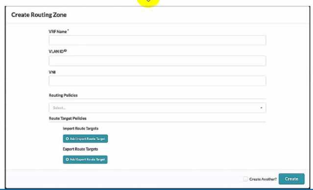
Referring to the exhibit, what is the minimum information you must add to create a new routing
zone?
- A. VRF Name only
- B. VRF Name and Routing policies
- C. VRF Name, VLAN ID. And VNI
- D. VRF Name, VLAN ID, VNI, Routing Policies
Answer:
C
Explanation:
To create a new routing zone, you must specify the VRF Name, VLAN ID, and VNI for the routing zone.
These are the mandatory fields in the user interface shown in the exhibit. The VRF Name is the name
of the L3 domain that isolates the IP traffic of the routing zone from other routing zones. The VLAN ID
is the identifier for the VLAN tagged Layer 3 links on external connections. The VNI is the VxLAN
Network Identifier associated with the routing zone. The Routing Policies are optional fields that
allow you to configure import and export route targets for the routing zone. These are only
applicable for EVPN routing zones, which use MP-EBGP as the overlay control protocol. The other
options are incorrect because:
A) VRF Name only is wrong because you also need to specify the VLAN ID and VNI for the routing
zone.
B) VRF Name and Routing policies is wrong because you also need to specify the VLAN ID and VNI for
the routing zone. Routing policies are optional and only relevant for EVPN routing zones.
D) VRF Name, VLAN ID, VNI, Routing Policies is wrong because Routing Policies are optional and not
required to create a new routing zone. Reference:
Routing Zones (Virtual)
Data Center Automation Using Juniper Apstra
Comments
Question 3
Which two statements are correct about Time Voyager? {Choose two.)
- A. Time Voyager retains all of the blueprint revisions from the last Juniper Apstra backup.
- B. Time Voyager retains the five most recent blueprint commits.
- C. Time Voyager retains the last ten blueprint commits.
- D. Time Voyager retains up to twenty-five saved revisions.
Answer:
BD
Explanation:
Time Voyager is a feature of Juniper Apstra that allows you to restore previous revisions of a
blueprint, which is a logical representation of your network design and configuration. Time Voyager
automatically saves the five most recent blueprint commits, which are the changes that you apply to
the network. You can also manually save up to twenty-five revisions by keeping them, which
prevents them from being overwritten by new commits. Therefore, the correct answer is B and D.
Time Voyager retains the five most recent blueprint commits and Time Voyager retains up to twenty-
five saved revisions. Reference:
Time Voyager | Apstra 4.1 | Juniper Networks
,
Time Voyager
Introduction | Apstra 4.2 | Juniper Networks
,
Juniper Apstra at a Glance | Flyer
Comments
Question 4
In the Juniper Apstra Ul. which three resources are assigned under the Resources menu? (Choose
three.)
- A. VTEP pools
- B. ASN pools
- C. VNI pools
- D. logical device pools
- E. IP address pools
Answer:
BCE
Explanation:
In the Juniper Apstra UI, the Resources menu allows you to create and manage global and local
resources that are used for various elements of the network design and configuration. The Resources
menu includes the following three types of resources that can be assigned to the network devices
and virtual networks:
ASN pools: These are pools of autonomous system numbers (ASNs) that are used for the underlay
routing protocol (EBGP) between the leaf and spine devices. You can create ASN pools with either 2-
byte or 4-byte ASNs, and assign them to the logical devices in the blueprint.
VNI pools: These are pools of virtual network identifiers (VNIs) that are used for the overlay network
(VXLAN) between the end hosts. You can create VNI pools with a range of VNIs, and assign them to
the virtual networks in the blueprint.
IP address pools: These are pools of IPv4 or IPv6 addresses that are used for various purposes in the
network, such as the loopback addresses for the devices, the IP prefixes for the virtual networks, the
host IP addresses for the end hosts, and the gateway IP addresses for the IRB interfaces. You can
create IP address pools with a range of IP addresses, and assign them to the logical devices and
virtual networks in the blueprint.
The following two types of resources are not assigned under the Resources menu:
VTEP pools: These are not resources that can be created or assigned by the user. VTEPs are VXLAN
tunnel endpoints that are automatically generated by the Apstra server based on the loopback IP
addresses of the devices. VTEPs are used as the source and destination IP addresses for the VXLAN
tunnels in the overlay network.
Logical device pools: These are not resources that can be created or assigned by the user. Logical
device pools are groups of logical devices that share the same role, interface map, and resource
assignments in the blueprint. Logical device pools are used to simplify the network design and
configuration by applying the same settings to multiple devices.
Reference:
Resources Introduction
ASN Pools (Resources)
VNI Pools (Resources)
IP Address Pools (Resources)
Comments
Question 5
In Juniper Apstr
a. which three modes are available for devices? (Choose three.)
- A. Deploy
- B. Active
- C. Stopped
- D. Drain
- E. Ready
Answer:
ADE
Explanation:
Juniper Apstra supports three deploy modes for devices: Deploy, Drain, and Ready.
These modes
determine the configuration and state of the devices in the data center fabric12
.
Deploy: This mode applies the full Apstra-rendered configuration to the device, according to the
Apstra Reference Design.
The device state becomes IS-ACTIVE and the device is ready to carry traffic
in the fabric12
.
Drain: This mode adds a “drain” configuration to the device, which prevents any new traffic from
entering the device.
The device state becomes IS-READY and the device is prepared for maintenance
or decommissioning12
.
Ready: This mode removes the Apstra-rendered configuration from the device, leaving only the basic
configuration such as device hostname, interface descriptions, and port speed/breakout.
The device
state becomes IS-READY and the device is not part of the fabric12
. Reference:
Device Configuration Lifecycle
Set Deploy Mode (Datacenter)
Comments
Question 6
You must configure a static route for traffic to exit a configured routing zone. In the Juniper Apstra Ul.
where would you accomplish this task?
- A. under Active -> Virtual -> Routing Zones
- B. under Staged -> Virtual -> Routing Zones
- C. under Active -> Connectivity Templates
- D. under Staged -> Connectivity Templates
Answer:
D
Explanation:
To configure a static route for traffic to exit a configured routing zone, you need to use the
Connectivity Templates feature in the Juniper Apstra UI. A Connectivity Template is a set of
configuration parameters that can be applied to a device or a group of devices in a blueprint. You can
use Connectivity Templates to configure static routes, BGP, OSPF, and other network services. To
create a Connectivity Template, you need to go to the Staged tab and select Connectivity Templates
from the left menu. Then, you can click on the + icon to create a new template. You can specify the
name, description, and scope of the template. The scope determines which devices or device groups
the template will be applied to. You can also specify the order of the template, which determines the
priority of the template when multiple templates are applied to the same device. After creating the
template, you can add configuration items to the template. To add a static route, you need to select
Static Route from the drop-down menu and enter the destination network, subnet mask, and next-
hop IP address. You can also specify the administrative distance and the track object for the static
route. After adding the configuration items, you need to save the template and commit the changes
to the blueprint. The other options are incorrect because:
A) under Active -> Virtual -> Routing Zones is wrong because this option allows you to view and
modify the existing routing zones, but not to configure static routes for them.
B) under Staged -> Virtual -> Routing Zones is wrong because this option allows you to create and
delete routing zones, but not to configure static routes for them.
C) under Active -> Connectivity Templates is wrong because this option allows you to view the
existing connectivity templates, but not to create or modify them. Reference:
Connectivity Templates
Data Center Automation Using Juniper Apstra
Comments
Question 7
Which fabric type should be chosen in a template to create a five-stage Clos?
- A. collapsed
- B. circuit switched
- C. rack-based
- D. pod-based
Answer:
D
Explanation:
According to the Juniper documentation1
, a five-stage Clos architecture allows for large-scale
topologies with an additional aggregation layer that interconnects multiple pods into a single fabric.
A pod is a group of racks that share the same spine devices. A rack is a group of leaf devices that
connect to the same servers. To create a five-stage Clos network using Juniper Apstra, you need to
choose the pod-based fabric type in the template creation wizard. This will allow you to specify the
number of pods, planes, spines, and leaves for your network design. Therefore, the correct answer is
D. pod-based. Reference:
5-Stage Clos Architecture | Apstra 4.1 | Juniper Networks
Comments
Question 8
Exhibit.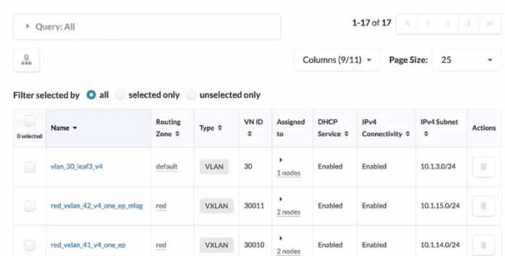
Referring to the exhibit, how do you display the IPv6 subnets lot all of the listed VXLANs?
- A. IPv6 subnets ate shown when each VXLAN is selected individually.
- B. Select Columns, then select IPv6 Subnet.
- C. Select all VXLANs. and the IPv6 Subnets column will appear
- D. An IPv6 Subnets column is not shown, indicating that no VXLAN has an assigned IPv6 subnet
Answer:
B
Explanation:
Referring to the exhibit, the image shows a user interface of the Juniper Apstra software application,
which is used for network management and configuration. The image shows the Virtual Networks
table under the Resources menu, which displays the details of the VLANs and VXLANs in the network.
The table has 11 columns, but only 9 are visible in the image. The other two columns are IPv6
Connectivity and IPv6 Subnet, which are hidden by default. To display the IPv6 subnets for all of the
listed VXLANs, the user needs to select Columns, then select IPv6 Subnet. This will show the IPv6
Subnet column in the table, which will display the IPv6 addresses assigned to the VXLANs from the
IPv6 pools. For more information, see
Virtual Networks (Resources)
. Reference:
Virtual Networks (Resources)
IPv6 Pools (Resources)
Apstra User Guide
Comments
Question 9
You want to apply a configlet to a specific device using Juniper Apstr
a. Which two parameters would be used to accomplish this task? (Choose two.)
- A. form factor
- B. hostname
- C. port group
- D. tags
Answer:
BD
Explanation:
To apply a configlet to a specific device using Juniper Apstra, you need to specify the device’s
hostname and tags. The hostname is the unique identifier of the device in the Apstra system, and the
tags are the labels that you can assign to the device to group it with other devices that share the
same characteristics.
You can use the hostname and tags to filter the devices that you want to apply
the configlet to in the blueprint catalog12
. Reference:
Configlets Overview
Terraform Registry
Comments
Question 10
What does EVPN use lo identity which remote leaf device advertised the EVPN route?
- A. a route distinguisher value
- B. a community tag
- C. a route target value
- D. a VRF target value
Answer:
A
Explanation:
EVPN uses a route distinguisher (RD) value to identify which remote leaf device advertised the EVPN
route. An RD is a 64-bit value that is prepended to the EVPN NLRI to create a unique VPNv4 or VPNv6
prefix. The RD value is usually derived from the IP address of the PE that originates the EVPN route.
By comparing the RD values of different EVPN routes, a PE can determine which remote PE
advertised the route and which VRF the route belongs to. The other options are incorrect because:
B) a community tag is wrong because a community tag is an optional transitive BGP attribute that
can be used to group destinations that share some common properties. A community tag does not
identify the source of the EVPN route.
C) a route target value is wrong because a route target (RT) value is an extended BGP community that
is used to control the import and export of EVPN routes between VRFs. An RT value does not identify
the source of the EVPN route.
D) a VRF target value is wrong because there is no such thing as a VRF target value in EVPN. A VRF is a
virtual routing and forwarding instance that isolates the IP traffic of different VPNs on a PE. A VRF
does not have a target value associated with it. Reference:
EVPN Fundamentals
RFC 9136 - IP Prefix Advertisement in Ethernet VPN (EVPN)
EVPN Type-5 Routes: IP Prefix Advertisement
Understanding EVPN Pure Type 5 Routes
Comments
Page 1 out of 6
Viewing questions 1-10 out of 65
page 2