Question 1
You are deploying a bonded 40 MHz wide channel What is the difference in the noise floor perceived
by a client using this bonded channel as compared to an unbonded 20MHz wide channel?
- A. 2dB
- B. 3dB
- C. 8dB
- D. 4dB
Answer:
B
Explanation:
The difference in the noise floor perceived by a client using a bonded 40 MHz wide channel as
compared to an unbonded 20 MHz wide channel is 3 dB. The noise floor is the level of background
noise in a given frequency band. When two adjacent channels are bonded, the noise floor increases
by 3 dB because the bandwidth is doubled and more noise is captured. The other options are
incorrect because they do not reflect the correct relationship between bandwidth and noise floor.
Reference: https://www.arubanetworks.com/techdocs/ArubaOS_86_Web_Help/Content/arubaos-
solutions/wlan-rf/rf-fundamentals.htm
https://www.arubanetworks.com/techdocs/ArubaOS_86_Web_Help/Content/arubaos-
solutions/wlan-rf/channel-bonding.htm
Comments
Question 2
When setting up an Aruba CX VSX pair, which information does the Inter-Switch Link Protocol
configuration use in the configuration created?
- A. QSVI
- B. MAC tables
- C. UDLD
- D. RPVST+
Answer:
B
Explanation:
The information that the Inter-Switch Link Protocol configuration uses in the configuration created is
B. MAC tables.
The Inter-Switch Link Protocol (ISL) is a protocol that enables the synchronization of data and state
information between two VSX peer switches. The ISL uses a version control mechanism and provides
backward compatibility regarding VSX synchronization capabilities.
The ISL can span long distances
(transceiver dependent) and supports different speeds, such as 10G, 25G, 40G, or 100G1
.
One of the data components that the ISL synchronizes is the MAC table, which is a database that
stores the MAC addresses of the devices connected to the switch and the corresponding ports or
VLANs.
The ISL ensures that both VSX peers have the same MAC table entries and can forward traffic
to the correct destination2
.
The ISL also synchronizes other data components, such as ARP table,
LACP states for VSX LAGs, and MSTP states2
.
Comments
Question 3
What is true regarding 802.11k?
- A. It extends radio measurements to define mechanisms for wireless network management of stations
- B. It reduces roaming delay by pre-authenticating clients with multiple target APs before a client roams to an AP
- C. It provides mechanisms for APs and clients to dynamically measure the available radio resources.
- D. It considers several metrics before it determines if a client should be steered to the 5GHz band, including client RSSI
Answer:
C
Explanation:
802.11k is a standard that provides mechanisms for APs and clients to dynamically measure the
available radio resources in a wireless network. 802.11k defines radio resource management (RRM)
functions, such as neighbor reports, link measurement, beacon reports, etc., that allow APs and
clients to exchange information about the RF environment and make better roaming decisions. The
other options are incorrect because they describe other standards, such as 802.11r, 802.11v, or
802.11ax. Reference: https://www.arubanetworks.com/assets/wp/WP_WiFi6.pdf
https://www.arubanetworks.com/assets/ds/DS_AP510Series.pdf
Comments
Question 4
Your customer is interested in hearing more about how roles can help keep consistent policy
enforcement in a distributed overlay fabric How would you explain this concept to them''
- A. Group Based Policy ID is applied on egress VTEP after device authentication and policy is enforced on ingress VTEP
- B. Role-based policies are tied to IP addresses which have an advantage over IP-based policies and role names are sent between VTEPs
- C. Group Based Policy ID is applied on ingress VTEP after device authentication and policy is enforced on egress VTEP
- D. Role-based policies enhance User Based Tunneling across the campus network and the policy traffic is protected with iPsec
Answer:
C
Explanation:
This is the correct explanation of how roles can help keep consistent policy enforcement in a
distributed overlay fabric. Roles are used to assign group based policy IDs (GBPs) to devices after
they authenticate with ClearPass or a local database. GBPs are then used to tag the traffic from the
devices and send them to the ingress VTEP, which applies the GBP on the VXLAN header. The egress
VTEP then enforces the policy based on the GBP and the destination device. The other options are
incorrect because they either do not describe the correct sequence of events or do not use the
correct terms. Reference: https://www.arubanetworks.com/techdocs/AOS-CX/10.04/HTML/5200-6728/bk01-ch03.html
https://www.arubanetworks.com/techdocs/AOS-CX/10.04/HTML/5200-6728/bk01-ch05.html
Comments
Question 5
How is Multicast Transmission Optimization implemented in an HPE Aruba wireless network?
- A. "The optimal rate for sending multicast frames is based on the highest broadcast rate across all associated clients
- B. When this option is enabled the minimum default rate for multicast traffic is set to 12 Mbps for 5 GHz
- C. The optimal rate for sending multicast frames is based on the lowest broadcast rate across all associated clients.
- D. The optimal rate for sending multicast frames is based on the lowest unicast rate across all associated clients.
Answer:
D
Explanation:
multicast transmission optimization is a feature that allows the IAP to select the optimal rate for
sending broadcast and multicast frames based on the lowest of unicast rates across all associated
clients1
. When this option is enabled, multicast traffic can be sent at up to 24 Mbps. The default rate
for sending frames for 2.4 GHz is 1 Mbps and 5.0 GHz is 6 Mbps.
This option is disabled by default1
.
Comments
Question 6
You are setting up a customer's 15 headless loT devices that do not support 802.1X. What should you
use?
- A. Multiple Pre-Shared Keys (MPSK) Local
- B. Clearpass with WPA3-PSK
- C. Clearpass with WPA3-AES
- D. Multiple Pre-Shared Keys (MPSK) with WPA3-AES
Answer:
A
Explanation:
MPSK Local is a feature that can be used to set up 15 headless IoT devices that do not support 802.1X
authentication. MPSK Local allows the switch to automatically generate and assign unique pre-
shared keys for devices based on their MAC addresses, without requiring any configuration on the
devices or an external authentication server. The other options are incorrect because they either
require 802.1X authentication, which is not supported by the IoT devices, or WPA3 encryption, which
is not supported by Aruba CX switches. Reference: https://www.arubanetworks.com/techdocs/AOS-CX/10.04/HTML/5200-6728/bk01-ch05.html
https://www.arubanetworks.com/techdocs/AOS-CX/10.04/HTML/5200-6728/bk01-ch06.html
Comments
Question 7
How do you allow a new VLAN 100 between VSX pair inter-switch-link 256 for port 1/45 and 2/45?
- A. vlan trunk allowed 100 for ports 1/45 and 1/46
- B. vlan trunk add 100 in LAG256
- C. vlan trunk allowed 100 in LAG256
- D. vlan trunk add 100 in MLAG256
Answer:
C
Explanation:
To allow a new VLAN 100 between VSX pair inter-switch-link 256 for port 1/45 and 2/45, you need to
use the command vlan trunk allowed 100 in LAG256. This will add VLAN 100 to the list of allowed
VLANs on the trunk port LAG256, which is part of the inter-switch-link between VSX peers. The other
options are incorrect because they either do not use the correct command or do not specify the
correct port or VLAN. Reference: https://www.arubanetworks.com/techdocs/AOS-CX/10.04/HTML/5200-6728/bk01-ch07.html
https://www.arubanetworks.com/techdocs/AOS-CX/10.04/HTML/5200-6728/bk01-ch02.html
Comments
Question 8
Two AOS-CX switches are configured with VSX at the the Access-Aggregation layer where servers
attach to them An SVI interface is configured for VLAN 10 and serves as the default gateway for VLAN
10. The ISL link between the switches fails, but the keepalive interface functions. Active gateway has
been configured on the VSX switches.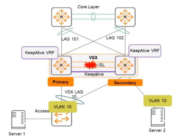
What is correct about access from the servers to the Core? (Select two.)
- A. Server 1 can access the core layer via the keepalrve link
- B. Server 2 can access the core layer via the keepalive link
- C. Server 2 cannot access the core layer.
- D. Server 1 can access the core layer via both uplinks
- E. Server 1 and Server 2 can communicate with each other via the core layer
- F. Server 1 can access the core layer on only one uplink
Answer:
DE
Explanation:
These are the correct statements about access from the servers to the Core when the ISL link
between the switches fails, but the keepalive interface functions. Server 1 can access the core layer
via both uplinks because it is connected to VSX-A, which is still active for VLAN 10. Server 2 can also
access the core layer via its uplink to VSX-B, which is still active for VLAN 10 because of Active
Gateway feature. Server 1 and Server 2 can communicate with each other via the core layer because
they are in the same VLAN and subnet, and their traffic can be routed through the core switches. The
other statements are incorrect because they either describe scenarios that are not possible or not
relevant to the question. Reference: https://www.arubanetworks.com/techdocs/AOS-
CX/10.04/HTML/5200-6728/bk01-
Comments
Question 9
A large retail client is looking to generate a rich set of contextual data based on the location
information of wireless clients in their stores Which standard uses Round Trip Time (RTT) and Fine
Time Measurements (FTM) to calculate the distance a client is from an AP?
- A. 802.11ah
- B. 802.11mc
- C. 802.11be
- D. 802.11V
Answer:
B
Explanation:
802.11mc is a standard that uses Round Trip Time (RTT) and Fine Time Measurements (FTM) to
calculate the distance a client is from an AP. 802.11mc defines a protocol for exchanging FTM frames
between an AP and a client, which contain timestamps that indicate when the frames were
transmitted and received. By measuring the RTT of these frames, the AP or the client can estimate
their distance based on the speed of light. The other options are incorrect because they either do not
use RTT or FTM or do not exist as standards. Reference:
https://www.arubanetworks.com/assets/wp/WP_WiFi6.pdf
https://www.arubanetworks.com/assets/ds/DS_AP510Series.pdf
Comments
Question 10
You need to create a keepalive network between two Aruba CX 8325 switches for VSX configuration
How should you establish the keepalive connection?
- A. SVI, VLAN trunk allowed all on ISL in default VRF
- B. routed port in custom VRF
- C. loopback 0 and OSPF area 0 in default VRF
- D. SVI, VLAN trunk allowed all on ISL in custom VRF
Answer:
B
Explanation:
To establish a keepalive connection between two Aruba CX 8325 switches for VSX configuration, you
need to use a routed port in custom VRF. A routed port is a physical port that acts as a layer 3
interface and does not belong to any VLAN. A custom VRF is a virtual routing and forwarding instance
that provides logical separation of routing tables. By using a routed port in custom VRF, you can
isolate the keepalive traffic from other traffic and prevent routing loops or conflicts. The other
options are incorrect because they either do not use a routed port or do not use a custom VRF.
Reference: https://www.arubanetworks.com/techdocs/AOS-CX/10.04/HTML/5200-6728/bk01-ch07.html
https://www.arubanetworks.com/techdocs/AOS-CX/10.04/HTML/5200-6728/bk01-ch02.html
Comments
Page 1 out of 13
Viewing questions 1-10 out of 139
page 2