Question 1
A volume has a snapshot policy assigned and snapshot creation is failing What is the cause of this
issue?
- A. The requested snapshot is 126th in the vTree.
- B. The snapshot name does not match the source volume.
- C. The snapshot is the 61st created by the policy
- D. The storage pool has 32 000 volumes plus snapshots and is at its limit
Answer:
C
Explanation:
The cause of the snapshot creation failure when a volume has a snapshot policy assigned is likely
because the snapshot is the 61st created by the policy. According to Dell PowerFlex documentation,
of the 126 user-available snapshots per volume, sixty (60) can be used for policy-based snapshot
scheduling1. This means that if the policy attempts to create a snapshot beyond this limit, it will fail.
Here’s a step-by-step explanation of the issue:
Snapshot Policy Limit: Each volume in a PowerFlex system can have a maximum of 126 user-available
snapshots. For policy-based snapshot scheduling, the limit is 60 snapshots per volume1.
Policy-Based Snapshot Creation: When a snapshot policy is in place, it will automatically attempt to
create snapshots based on the defined schedule and retention levels.
Failure Point: If the snapshot policy tries to create a snapshot and it is the 61st snapshot for that
volume, the creation will fail because it exceeds the limit set for policy-based snapshots1.
Resolution: To resolve this issue, the administrator would need to adjust the snapshot policy to
ensure that it does not exceed the limit of 60 snapshots. This may involve modifying the retention
levels or the frequency of snapshot creation.
This explanation is based on the snapshot policy details provided in the Dell PowerFlex
documentation, which outlines the restrictions and uses of snapshots within the PowerFlex storage
system1.
Comments
Question 2
DRAG DROP
What is the correct sequence of steps to create an FG Storage Pool within a PowerFlex system?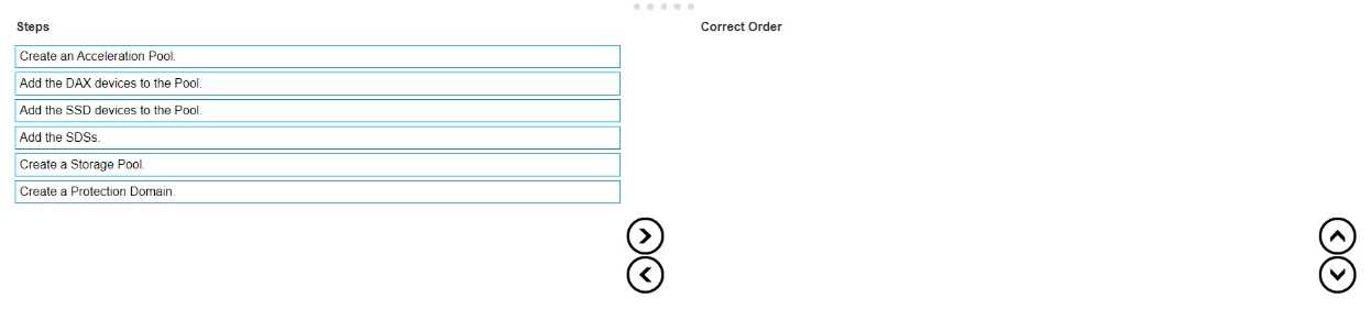
Answer:
None
Explanation:
The correct sequence of steps to create an FG (Fine Granularity) Storage Pool within a PowerFlex
system is as follows:
Create a Protection Domain: This is the first step, where you define a logical grouping of storage
resources that share the same protection policy and fault tolerance settings1.
Create a Storage Pool: After establishing a Protection Domain, you create a Storage Pool within
it. This pool will contain the physical storage resources1.
Add the SDSs (Storage Data Servers): The next step is to add SDSs to the Storage Pool. SDSs are the
servers that contribute storage capacity to the pool1.
Add the SSD (Solid-State Drive) devices to the Pool: Once the SDSs are added, you then add the SSD
devices to the Storage Pool to provide the actual storage capacity1.
Create an Acceleration Pool: This step involves creating an Acceleration Pool, which is used for
caching to enhance the performance of the storage system1.
Add the DAX (Direct Access) devices to the Pool: Finally, you add the DAX devices to the Acceleration
Pool. DAX devices are typically high-speed storage devices like NVMe drives that serve as cache
The process of creating an FG Storage Pool in a PowerFlex system involves a series of steps that
establish the necessary components and configurations for the storage environment. The sequence
starts with the creation of a Protection Domain, which sets the stage for defining how storage will be
protected and managed. Within this domain, a Storage Pool is created, which is essentially a
collection of storage resources. The SDSs are then added to this pool, contributing their storage
capacity to the overall system. SSD devices are included next to provide the actual storage space. An
Acceleration Pool is created to improve performance through caching, and DAX devices are added to
this pool to serve as the cache, completing the setup of an FG Storage Pool1.
This sequence ensures that the storage system is configured for optimal performance and data
protection, following the guidelines and best practices outlined in the PowerFlex documentation1.
It’s important to follow these steps in order to maintain the integrity and efficiency of the PowerFlex
storage system.
Comments
Question 3
A user is attempting to write tiles to a Power Flex File share The share was created with default
settings and contains approximately 15 000 files Ten days ago the number of files exceeded the soft
limit quota but is still below the hard limit quota What happens if the user attempts to write a new
file to the share location?
- A. The file is not written as the maximum number of allowed files has been reached
- B. The file is not written as the grace period has been exceeded.
- C. The file is written as the hard limit has not been reached.
Answer:
C
Explanation:
In PowerFlex File shares, when a soft limit quota is exceeded, it triggers a grace period during which
users can still write data to the share. The grace period is a predefined time frame that allows users
to either reduce the amount of stored data or to adjust the quota settings. As long as the hard limit
quota has not been reached, users can continue to write files to the share, even if the soft limit has
been exceeded and the grace period is in effect1.
The soft limit is essentially a warning threshold that alerts users that they are approaching the
maximum allowed capacity, but it does not immediately prevent new writes. The hard limit, on the
other hand, is a strict limit that, once reached, will prevent any further writes to the share until the
stored data is reduced below the hard limit or the quota is increased.
Since the question states that the number of files is still below the hard limit quota, the user will be
able to write a new file to the share location. Therefore, the correct answer is C. The file is written as
the hard limit has not been reached.
Comments
Question 4
DRAG DROP
Place the steps to set up remote replication on the Powerflex system in the correct order
Answer:
None
Explanation: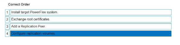
The correct sequence of steps to set up remote replication on the PowerFlex system is as follows:
Install target PowerFlex system: Before replication can be set up, there must be a target system in
place to receive the replicated data1.
Exchange root certificates: This is a security measure to ensure that communication between the
source and target systems is secure1.
Add a Replication Peer: This involves configuring the target system as a replication partner in the
source system’s configuration1.
Configure replication volumes: Finally, specific volumes on the source system are configured to
replicate to the target system1.
Setting up remote replication in a PowerFlex system involves a series of steps that establish the
necessary components and configurations for the replication process. The sequence begins with the
installation of the target PowerFlex system, which will serve as the destination for the replicated dat
a. Next, root certificates are exchanged between the source and target systems to ensure secure
communication. The target system is then added as a Replication Peer within the source system’s
configuration. Lastly, the volumes intended for replication are configured on the source system to
complete the setup process. This sequence ensures that the replication is secure, reliable, and
correctly configured to maintain data integrity and availability across both systems1.
Comments
Question 5
An administrator is adding an NVMe device to an existing storage pool They provide the following
details in the Add Storage Device to SDS dialog box
• Device Path /dev/disk/by-id'Dell_Express_Flash_NVMe_PM1725_V6TB_SFF_
_S2JPNA0J500141
- A. The device addition fails due to an invalid path
- B. The device is named "NVMeAt 6 TB" and added to the Storage Pool "SP-1".
- C. The device name is truncated to "NVMe" and added lo the Storage Pool "SP-t"
- D. The device addition tails due to invalid characters in the name
Answer:
A
Explanation:
When adding an NVMe device to an existing storage pool in PowerFlex, the details provided in the
“Add Storage Device to SDS” dialog box must be accurate and follow the correct syntax. In the
scenario provided, the device path contains an invalid character (an apostrophe) and an incorrect
format, which would cause the device addition to fail.
Here’s a breakdown of the process and where the error occurs:
Device Path: The device path should be a valid Linux device path, typically starting with /dev/disk/by-
id/. The path provided contains an apostrophe (') which is not a valid character in Linux file paths and
would result in an error1.
Device Name: The device name should be a simple identifier without spaces or special characters.
The name provided, “NVMe A. 1.6 TB”, contains spaces and periods, which are not typical for device
names and could potentially lead to issues, although the primary cause of failure is the invalid device
path1.
Storage Pool: The storage pool name “SP-1” is a valid identifier, but it is contingent on the correct
device path and name for the device to be added successfully.
The result of the action, given the invalid device path, would be that the device addition fails. It is
crucial to ensure that all details entered in the dialog box adhere to the expected formats and do not
contain invalid characters to avoid such failures.
This explanation is based on the standard practices for device path naming conventions in Linux
systems and the configuration guidelines for PowerFlex systems as described in Dell’s official
documentation1. Correcting the device path by removing the invalid character and ensuring the
proper format would resolve the issue and allow the device to be added to the storage pool
successfully.
Comments
Question 6
A customer has ordered five servers with NVDlMMs Each server has 5 x 3 84 TB SAS and 5 x 3 84 T8
NVMe disks They want to ensure that the highest capacity ot storage is available to the system Which
design provides the required storage pool structure''
- A. One Storage Pool and one Acceleration Pool
- B. One Acceleration Pool only
- C. One Storage Pool only
- D. One Acceleration Pool and two Storage Pools
Answer:
A
Explanation:
To maximize the storage capacity available to the system while utilizing NVDIMMs, SAS, and NVMe
disks, the design should include both a Storage Pool and an Acceleration Pool. The Storage Pool will
be used for the bulk storage provided by the SAS disks, while the Acceleration Pool, leveraging the
high-speed NVMe disks, will be used to accelerate the performance of the storage system.
The use of NVDIMMs in PowerFlex is associated with enabling fine-granularity storage pools that
provide compression, which is beneficial for space efficiency, especially with heavy snapshot use1.
This configuration allows for the creation of a storage pool that can take advantage of the NVDIMMs’
capabilities for compression and the high capacity of the SAS disks, while the NVMe disks in the
Acceleration Pool provide high-performance storage for more demanding workloads.
Therefore, the correct answer is A. One Storage Pool and one Acceleration Pool, as this design will
provide the highest capacity of storage available to the system while also ensuring optimal
performance through the use of NVMe disks in the Acceleration Pool.
Comments
Question 7
An administrator wants to configure SDTs to perform I/O with hosts that are going to use the NVMe
over Fabric protocol What are three requirements to accomplish this task (Select 3)
- A. The Storage port must be configured with the host role
- B. The Discovery port must be configured with the storage role
- C. The NVMe Qualified Name of the hosts is known
- D. A minimum of two NVMe targets must be assigned to a Protection Domain.
- E. The storage rote and hosts role must be configured to the same target IP addresses
Answer:
ACD
Explanation:
To configure Storage Data Targets (SDTs) for I/O operations with hosts using the NVMe over Fabric
protocol, the following requirements are necessary:
The Storage port must be configured with the host role: The storage port, which is part of the SDT,
needs to be configured to communicate with the host systems. This involves setting the port to
operate in the host role, which allows it to handle input/output operations with the hosts1.
The NVMe Qualified Name (NQN) of the hosts is known: The NQN is a unique identifier used in
NVMe over Fabrics to identify both NVMe targets and hosts. Knowing the NQN of the hosts is
essential for proper configuration and communication between the SDTs and the hosts1.
A minimum of two NVMe targets must be assigned to a Protection Domain: For redundancy and to
ensure continuous availability, it is recommended to have at least two NVMe targets assigned to a
Protection Domain. This allows for failover capabilities and load balancing across multiple paths1.
These requirements are based on the best practices for setting up NVMe over Fabric protocols as
outlined in the PowerFlex documentation and resources. Proper configuration of the storage ports,
knowledge of the NQN, and assignment of NVMe targets to a Protection Domain are crucial steps in
ensuring successful I/O operations with NVMe over Fabrics1.
Comments
Question 8
An administrator is using SCLI commands to monitor the cluster
On which MDM are the commands performed?
- A. Tie-breaKer
- B. Standby
- C. Primary
- D. Secondary
Answer:
C
Explanation:
In a PowerFlex system, the SCLI (ScaleIO Command Line Interface) commands are typically
performed on the Primary MDM (Metadata Manager). The Primary MDM is responsible for the
overall management and operation of the cluster, including configuration changes and monitoring1.
It is the authoritative source for metadata and cluster configuration, making it the primary point of
interaction for administrative tasks.
The Tie-breaker and Standby MDMs serve as part of the high availability setup. The Tie-breaker MDM
is used to avoid split-brain scenarios, and the Standby MDM is a backup that can take over the role of
the Primary MDM if it fails. The Secondary MDM works in conjunction with the Primary MDM to
manage the cluster but does not serve as the main point for executing SCLI commands.
Therefore, the correct answer is C. Primary, as it is the MDM where SCLI commands are executed for
monitoring and managing the PowerFlex cluster.
Comments
Question 9
Which PowerFlex component provides the information that application servers require to connect to
the cluster's virtualized storage?
- A. MDM
- B. SDC
- C. SDR
- D. SDS
Answer:
B
Explanation:
The PowerFlex component that provides the information application servers require to connect to
the cluster’s virtualized storage is the Storage Data Client (SDC). The SDC is installed on application
servers and is responsible for translating standard block I/O requests from the server’s operating
system into network I/O requests that can be understood and processed by the PowerFlex storage
cluster.
Here’s a detailed explanation:
SDC Role: The SDC acts as the interface between the application servers and the PowerFlex storage
system. It allows servers to access the virtualized storage as if it were local to the server1.
Connection Process: When an application server needs to connect to the PowerFlex cluster, the SDC
communicates with the Meta Data Manager (MDM) to understand the layout of the storage and then
interacts with the Storage Data Server (SDS) to perform I/O operations1.
Virtualized Storage Access: Through the SDC, application servers can perform read and write
operations on the virtualized storage volumes provided by the PowerFlex cluster, ensuring seamless
integration with the existing applications and services1.
The SDC is a critical component in the PowerFlex architecture, enabling the connection and
communication between application servers and the PowerFlex storage cluster, thus facilitating the
use of virtualized storage resources1.
Comments
Question 10
An engineer must permanently remove a node from a 10-node PowerFlex system The node is the
primary MDM. What must they do before they remove the node to avoid errors and maintain
availability'
- A. Use the renove_standby_imdm SCLI command
- B. Use the switch_ciuster_mcde SCLI command
- C. Use PowerFlex Manager to reconfigure MDM roles
- D. Use PowerFlex Manager to deactivate the Protection Domain.
Answer:
C
Explanation:
Before permanently removing a node that is the primary MDM from a PowerFlex system, it is crucial
to ensure that the MDM roles are reconfigured to maintain cluster availability and avoid errors. This
process involves promoting another node to take over the primary MDM role and ensuring that the
cluster continues to function correctly without the node that is being removed.
The steps to reconfigure MDM roles using PowerFlex Manager are as follows:
Log in to PowerFlex Manager.
Navigate to the MDM cluster settings.
Identify a suitable node that can be promoted to the primary MDM role.
Use the PowerFlex Manager interface to promote the selected node to the primary MDM role.
Ensure that the cluster is stable and that the new primary MDM is functioning correctly.
Once the new primary MDM is in place and operational, the original primary MDM node can be
safely removed from the cluster.
This process is essential to prevent any disruptions in the management and operation of the
PowerFlex system. The other options listed, such as using the remove_standby_mdm SCLI command
(Option A) or the switch_cluster_mode SCLI command (Option B), do not directly address the
reconfiguration of MDM roles. Deactivating the Protection Domain (Option D) is not related to the
removal of an MDM node and would not be a recommended step in this scenario.
Therefore, the correct answer is C. Use PowerFlex Manager to reconfigure MDM roles, as it ensures
that the MDM responsibilities are transferred to another node before the primary MDM node is
removed, thus maintaining the integrity and availability of the PowerFlex system1.
Comments
Page 1 out of 3
Viewing questions 1-10 out of 40
page 2