Question 1
What is the alert severity if the license expiration date is within a week?
- A. Minor
- B. Major
- C. Information
- D. Warning
Answer:
D
Explanation:
When the license expiration date is within a week, Dell PowerStore generates a warning-level alert.
This alert severity level is used to indicate that action should be taken soon to prevent potential
service disruptions or limitations on system functionality. A warning alert is not as severe as a major
alert, which would indicate immediate attention is required, but it is more critical than an
informational alert, which is typically used for general notifications without immediate impact.
The warning alert serves as a proactive reminder to renew or update the license to ensure
continuous operation of the PowerStore system.
It is important to address these alerts promptly to
maintain access to all features and avoid any limitations on system management operations1
.
For more information on alert severities and license management in Dell PowerStore, administrators
can refer to the PowerStore documentation on License State Alerts and the PowerStore Manager
Overview, which provide detailed explanations of the different alert levels and the steps to manage
and resolve licensing issues23
. Following the guidelines in these documents will help ensure that the
storage system remains fully operational and compliant with licensing requirements.
Comments
Question 2
Which component is only replaceable by qualified personnel?
- A. Base enclosure
- B. Memory module
- C. Embedded I/O module
- D. Power supply
Answer:
A
Explanation:
The base enclosure is a component that is typically only replaceable by qualified personnel. This is
because the base enclosure of a Dell PowerStore system contains critical components and
connections that require specialized knowledge and tools to handle properly. Replacing a base
enclosure involves understanding the system’s architecture, safely disconnecting and reconnecting
various components, and ensuring that the system is not compromised during the process.
The memory module, embedded I/O module, and power supply are designed to be more accessible
for replacement and may fall under the category of customer-replaceable units (CRUs) or field-
replaceable units (FRUs), depending on the specific model and configuration of the PowerStore
system1
.
For detailed procedures on replacing the base enclosure or any other components, it is
recommended to refer to the official Dell PowerStore Installation and Service Guide.
This guide
provides step-by-step instructions and safety precautions for qualified personnel to follow when
performing hardware replacements1
. It is crucial to adhere to these guidelines to maintain system
integrity and ensure that the storage system continues to operate effectively after the replacement.
Comments
Question 3
A Storage Administrator needs to address specific fixes within their Dell EMC PowerStore system.
Which NDU software upgrade option is used for this situation?
- A. Drive firmware
- B. Hotfixes
- C. Software releases
- D. vCenter
Answer:
B
Explanation:
In the context of Dell EMC PowerStore, when a Storage Administrator needs to address specific fixes
within their system, the appropriate Non-Disruptive Upgrade (NDU) software upgrade option to use
is Hotfixes.
Hotfixes are targeted software updates that address specific issues or bugs within the
system without requiring a full software release upgrade1
.
The process for applying hotfixes typically involves:
Identifying the specific issue and the corresponding hotfix that addresses it.
Downloading the hotfix from the Dell Support website or through the PowerStore Manager interface.
Applying the hotfix to the PowerStore system using the NDU process, which ensures that the system
remains operational and accessible during the upgrade.
Verifying that the hotfix has been applied successfully and that the issue has been resolved.
It is important to follow the detailed instructions provided in the Dell PowerStore Software Upgrade
Guide when applying hotfixes.
This guide outlines the steps for preparing for an NDU, including any
preliminary checks and concluding checks to ensure the integrity of the upgrade process2
.
Administrators should also consult the PowerStore Release Notes to determine which software
upgrade packages, including hotfixes, are required for their specific PowerStore model and
configuration2
. Adhering to these guidelines helps ensure that the system is updated correctly and
that the specific fixes are applied effectively.
Comments
Question 4
What is the maximum number of expansion enclosures that a single Dell EMC PowerStore 9000T
appliance supports?
- A. 8
- B. 3
- C. 4
- D. 2
Answer:
B
Explanation:
The maximum number of expansion enclosures that a single Dell EMC PowerStore 9000T appliance
supports is three.
This is consistent with the design and specifications provided by Dell for the
PowerStore series, which allows for scalability within the storage environment1
.
The expansion enclosures are used to increase the storage capacity of the PowerStore system beyond
what is available in the base enclosure. Each expansion enclosure connects to the base appliance and
adds additional drive slots for storage expansion.
For detailed information on the configuration and limitations of expansion enclosures for the
PowerStore 9000T model, administrators should refer to the official Dell PowerStore Hardware
Information Guide and the Dell PowerStore Technical Primer.
These documents provide
comprehensive guidelines on the physical and logical expansion capabilities of the PowerStore
systems23
. Adhering to these specifications is crucial to ensure proper system performance and to
avoid unsupported configurations.
Comments
Question 5
Which number in the code-naming schema represents a beta distribution?
- A. 5
- B. 4
- C. 6
- D. 8
Answer:
B
Explanation:
In the Dell PowerStore code-naming schema, the number that represents a beta distribution is 4.
This is based on the PowerStoreOS release matrix, where the versioning and distribution types are
indicated by specific digits in the version number.
The third digit in the version number typically
represents the target code, which is a highly trusted and recommended release1
.
For beta distributions, which are pre-release versions provided for testing purposes, Dell uses specific
numbering conventions to distinguish them from general availability releases. These beta versions
are important for testing new features and fixes in a controlled environment before they are released
to all customers.
For detailed information on the code-naming schema and understanding the different types of
software distributions for Dell PowerStore, including beta distributions, administrators should refer
to the official Dell PowerStoreOS Matrix documentation.
This document provides a comprehensive
overview of the versioning system and the criteria used to determine the target code and other
distribution types1
.
Comments
Question 6
DRAG DROP
Correctly order the steps of the embedded module replacement procedure.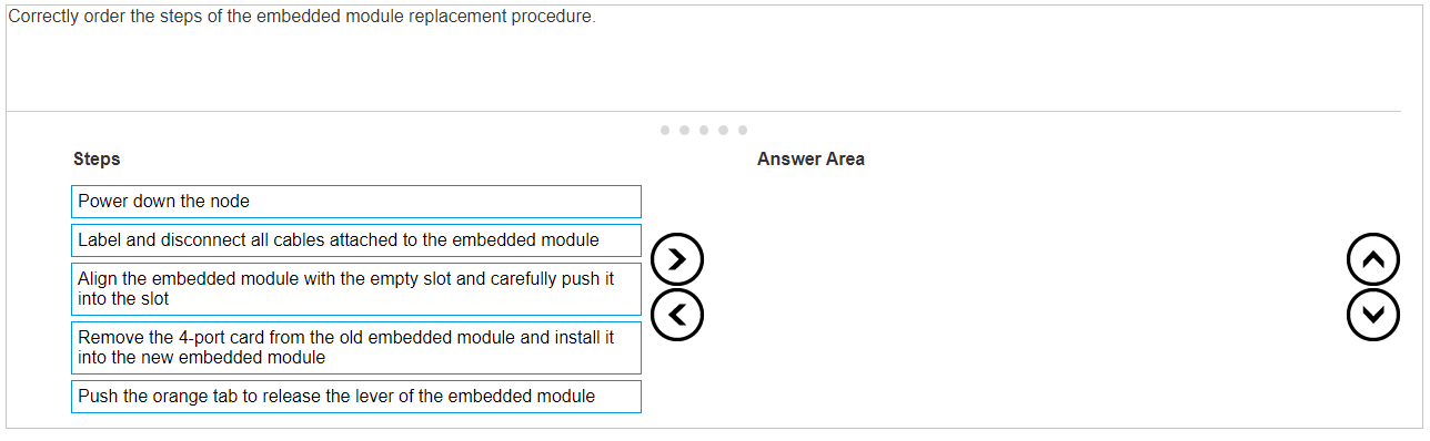
Answer:
None
Explanation: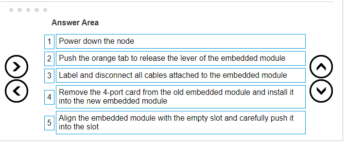
The correct order of steps for the embedded module replacement procedure is:
Power down the node
Push the orange tab to release the lever of the embedded module
Label and disconnect all cables attached to the embedded module
Remove the 4-port card from the old embedded module and install it into the new embedded
module
Align the embedded module with the empty slot and carefully push it into the slot
The procedure for replacing an embedded module in a Dell PowerStore system is a critical task that
should be performed with care. Here is a detailed explanation of each step:
Power down the node: Ensure that the node is properly powered down to avoid any electrical
hazards or data corruption.
This step is crucial for the safety of both the technician and the system1
.
Push the orange tab to release the lever of the embedded module: Locate the orange tab on the
embedded module and push it to release the lever.
This action will unlock the module from its slot1
.
Label and disconnect all cables attached to the embedded module: Before removing the embedded
module, label all cables for easy reconnection later.
Then, carefully disconnect each cable to free the
module1
.
Remove the 4-port card from the old embedded module and install it into the new embedded
module: Transfer the 4-port card from the old module to the new one.
Handle the card with care to
avoid damage to the electronic components1
.
Align the embedded module with the empty slot and carefully push it into the slot: Carefully align
the new embedded module with the guides in the empty slot and gently push it into place until it is
securely seated1
.
After completing these steps, reconnect the cables as per the labels, and power up the node to verify
the operation of the new embedded module.
For detailed instructions and safety information, refer
to the Dell PowerStore Installation and Service Guide2
. It is important to follow these guidelines
closely to ensure the replacement is performed correctly and the system operates smoothly after the
procedure.
Comments
Question 7
DRAG DROP
Match the base enclosure SAS ports in column A to their corresponding expansion enclosure LCC
ports in column B; when connecting a PowerStore base enclosure to a single expansion enclosure.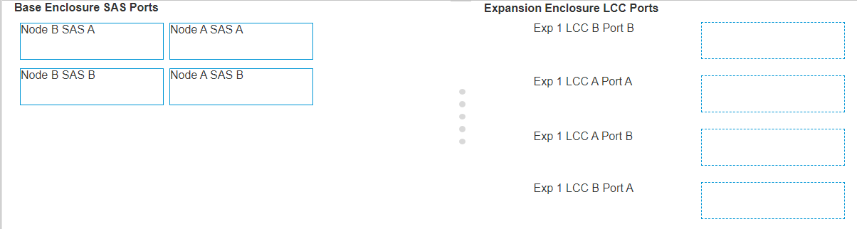
Answer:
None
Explanation:
To match the base enclosure SAS ports in column A to their corresponding expansion enclosure LCC
ports in column B for a Dell PowerStore base enclosure connected to a single expansion enclosure,
the correct configuration is:
Node B SAS A to Exp 1 LCC A Port B
Node A SAS A to Exp 1 LCC B Port A
Node B SAS B to Exp 1 LCC A Port A
Node A SAS B to Exp 1 LCC B Port B
Step by Step Comprehensive Detailed Explanation with Reference
Identify the SAS ports on the base enclosure and the LCC ports on the expansion enclosure.
Match the ports according to the configuration provided above.
Connect the cables between the corresponding SAS and LCC ports.
Secure the connections to ensure there is no loose cabling.
Verify the configuration using the PowerStore Manager to ensure all connections are recognized and
functioning properly.
For detailed instructions, diagrams, and best practices, refer to the Dell PowerStore Installation and
Service Guide1, as well as the Dell EMC PowerStore Quick Start Guide2
. These documents provide
essential information on the proper setup and maintenance of the storage system, ensuring optimal
performance and reliability.
Comments
Question 8
While on-site installing a Dell EMC PowerStore T system, the node A embedded module
management Ethernet port link LED is off. What does this indicate?
- A. Port speed is 10 GB/s
- B. Network connection is established
- C. Port speed is 1 GB/S
- D. No network connection is established
Answer:
D
Explanation:
When the link LED of the node A embedded module management Ethernet port is off, it indicates
that there is no network connection established. The link LED is typically used to indicate the
presence of a network connection and its status.
If the LED is off, it means that the Ethernet port is
not currently connected to a network or there is an issue preventing the connection from being
established1
.
In the case of the Dell EMC PowerStore T system, the embedded module management Ethernet
ports are used for network management traffic. It is essential that these ports have an active
network connection for the system to be managed remotely. If the link LED is off, the following steps
should be taken:
Check the physical connection of the Ethernet cable to ensure it is securely plugged into both the
node’s port and the corresponding switch or router port.
Verify that the switch or router is powered on and functioning correctly.
Ensure that the correct port on the switch or router is being used and that it is configured correctly
for the PowerStore system.
If the issue persists after checking the physical connections and switch/router configuration, consult
the Dell EMC PowerStore T Installation and Service Manual for further troubleshooting steps2
.
It is important to resolve any network connection issues promptly to maintain the manageability and
accessibility of the PowerStore system. Following the official Dell documentation and support
resources will help ensure that the system is installed and configured correctly for optimal
performance and reliability.
Comments
Question 9
How is a service laptop IP configured to connect to the Service LAN port of a Dell EMC PowerStore
node?
- A. Static IP: 169.254.1.249 and netmask: 255.0.0.0
- B. Leave IP address and netmask unconfigured
- C. Static IP: 128.221.1.249 and netmask: 255.255.255.0
- D. Obtain IP address from DHCP on PowerStore
Answer:
C
Explanation:
To connect a service laptop to the Service LAN port of a Dell EMC PowerStore node, the laptop’s
Ethernet interface should be configured with a static IP address and netmask. The correct
configuration is:
IP: 128.221.1.249
Netmask: 255.255.255.0
Gateway: None1
This configuration allows the service laptop to communicate with the PowerStore nodes for SSH and
PowerStore Manager (UI) access. It’s important to note that the laptop can be physically connected
to one of the PowerStore nodes at a time, or to both nodes’ Service LAN ports using a small switch or
hub.
However, multiple appliances should never be connected to the same hub or switch as the
nodes use the same internal IPs1
.
Once the IP is configured as shown above and the physical connection is established, you can ping
the relevant IPs:
Node A: 128.221.1.250
Node B: 128.221.1.251
You should only be able to ping the IPs where you are physically connected to. If you can ping, you
can proceed to use SSH to connect to the IPs over port 22 using your preferred SSH client.
For file
transfers, SCP protocol must be used1
.
For more detailed instructions on how to connect to the system over the Service LAN Ports for SSH
and PowerStore Manager access, refer to the Dell Support Knowledge Base Article1
.
Comments
Question 10
Which reference source provides service information and FRU procedures for Dell EMC PowerStore?
- A. PowerStore Manager help
- B. DELL EMC PowerStore Product Page
- C. DELL EMC Online Support
- D. SolVe Tool
Answer:
D
Explanation:
The SolVe Tool is the reference source that provides service information and Field Replaceable Unit
(FRU) procedures for Dell EMC PowerStore.
The SolVe Tool is an online resource that offers step-by-
step guidance for various procedures, including servicing and replacing hardware components, also
known as FRUs1
.
The tool is designed to help users and service technicians perform maintenance tasks accurately and
efficiently. It includes detailed instructions, diagrams, and other helpful information that can assist in
troubleshooting and resolving issues with Dell EMC PowerStore systems.
For accessing the SolVe Tool and finding the service information and FRU procedures for PowerStore,
users can visit the Dell Support website and navigate to the SolVe Online section.
Additionally, the
PowerStore Info Hub provides a collection of product documentation and videos that can be useful
for understanding the system’s operation and maintenance2
.
It is important to use the SolVe Tool and follow the provided instructions carefully to ensure that any
service actions are performed correctly and safely, maintaining the integrity and performance of the
PowerStore system.
Comments
Page 1 out of 6
Viewing questions 1-10 out of 61
page 2